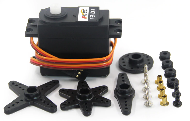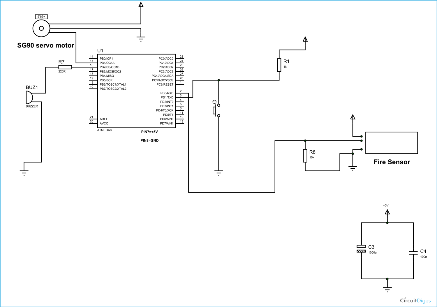

The arduino uno has a 10-bit analog to digital converter. The terminal(T1) of the potentiometer is connected to supply voltage and the other terminal(T2) to the ground.īy turning the potentiometer, the input voltage varies in the range of 0 to 5V. The wiper pin of the potentiometer is connected to analog input of the arduino. The servo moves clockwise or counterclockwise (0° – 180°) with the corresponding angular position of the potentiometer. At every instant, the servo arm follows the position of the Knob. Here we are controlling the angular position of a servo motor using a potentiometer. It connects to the ground pin of the Arduino. The ground wire typically has black or brown colour. And connect the supply terminal of the servo (+V) to the +Ve terminal of the external supply. Because the power at the remaining pins would be interrupted during its operation.įor external powering, connect the ground of the arduino commonly with the -ve terminal of the external power supply. So, for multiple servos or while using servos along with other pins, it is better to power the servo motor separately with an external supply. The Servo motor requires a considerable amount of power, especially for high power servos.

The power wire mostly has a red colour, which connects to the 5V pin of the Arduino. Servo motor interfacing with Arduino Power The servo motors are interfaced with the Arduino through a standard three-wire connection. Thus the pulse width between 1ms and 2ms obtains a corresponding position between 0° to 180° angles respectively. For a standard servo, 1ms positive pulse maintains a 0° and a maximum of the 2ms positive pulse will have a position of 180°. That is the duration of the positive pulse in a 20ms total pulse width determines the servo shaft position. The width of each pulse directs the servo to turn the shaft to the corresponding angular positions. The servo motor expects a control pulse at every 20 milliseconds (ms). The input pulse train at the control signal will turn the rotor to the desired position. If you just have a "defect" 180 degree servo turning to lets say 190 degree for some reason, you might try the microsecond method playing around with the values in attach, also use an extra power supply, but for real over 180 degree action get a 270 degree servo.The angular positions of a servo motor are controlled by the pulse width modulation(PWM). servo.attach(5,500,2500)ĪND you have to use an extra power supply for 270 degree servos, the 5V from Arduino want make them move or only in a jittering way of. If you want to control it more precicly you use microseconds. So if your servo is a 270 degree servo (like the domanrc DM-S0903MD or DS3218 270 Degree Digital RC Servo) the standard sweep sketch (Arduino Servo library) will let your servo sweep from 0-270 even if in the *.ino its myservo.write(180) So to simply test you could use write(map(desired_angle, 0, 270, 0, 180))

You can bring it to rest at any angle you desire by adjusting the pulse width accordingly.
Program servo motor arduino to rotate left by 30 degree full#
Varying the pulse width between 1ms and 2ms will move the servo shaft through the full 180 degrees of its travel. A pulse width of 2ms will cause the servo shaft to rest in the 180 degree position.A pulse width of 1ms will cause the servo shaft to rest at the 0 degree position.


 0 kommentar(er)
